Group assignment(Read more about the group assignment.)
Invidual assignment
For this week i need to design, build, and connect wired or wireless node(s) with network or bus addresses as a invidual assignment.I choose to do the serial communication with a bridge and a node.
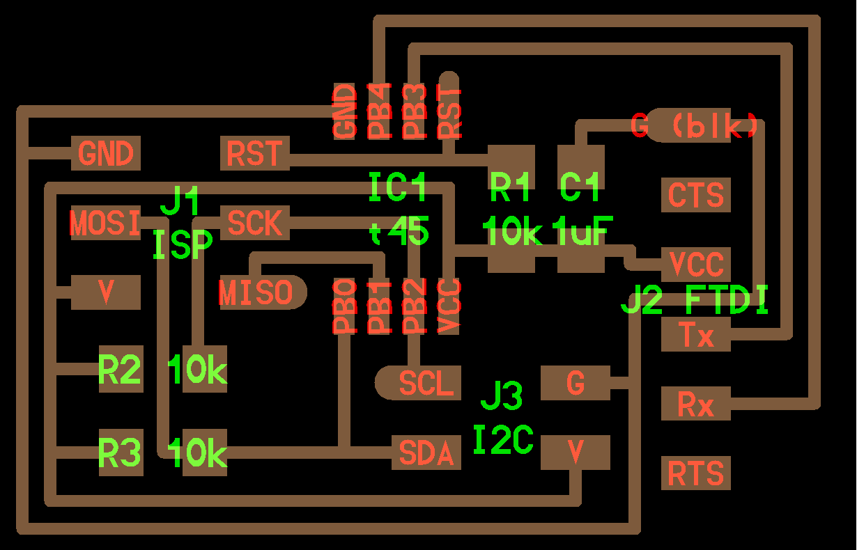
The Bridge board
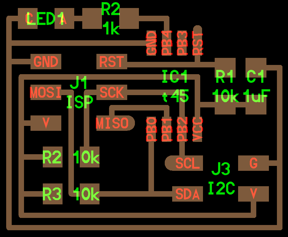
The Node board
Redesigning the board
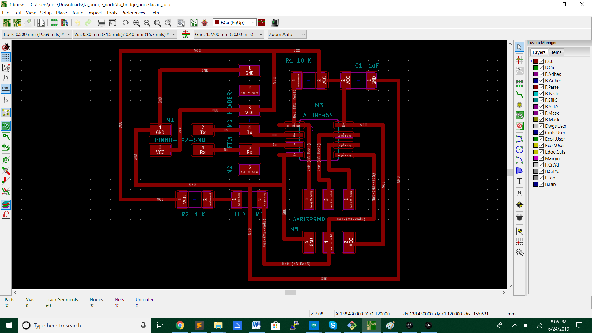
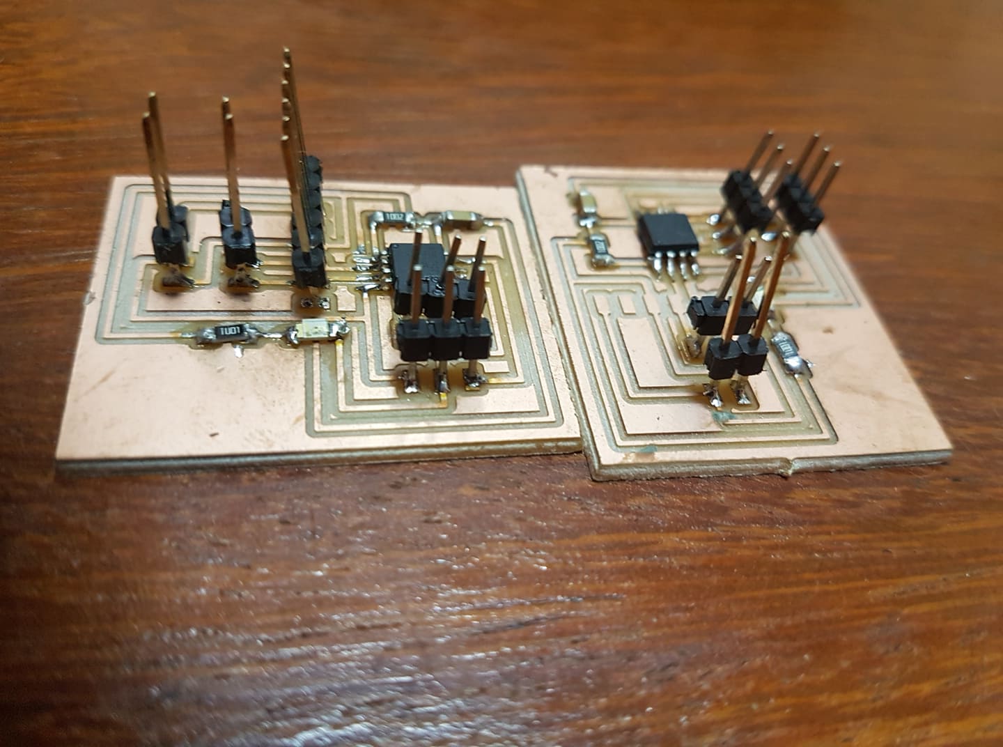
Looking at the Bridge and the Node board is that the only difference is the FTDI and the Bridge pin.So i redesigned the board with the same design.On one of the boards i soldered the FTDI pin and on the other board not.
Parameters for flatcam
| Parameters | Routes | Cut |
|---|---|---|
| Tool dia | 0.38 | 0.9 |
| Passes | 2 | 1 |
| Overlap | 0.6 | - |
| Cut Z | -0.15 | -1.5 |
| Multi-depth | No | Yes |
| Stepdown | - | 0.5 |
| Travel Z | 1.5 | 1.5 |
| Spindle | 2000 | 2000 |
| Feedrate | 1 | 1 |
| Margin | - | 2 |
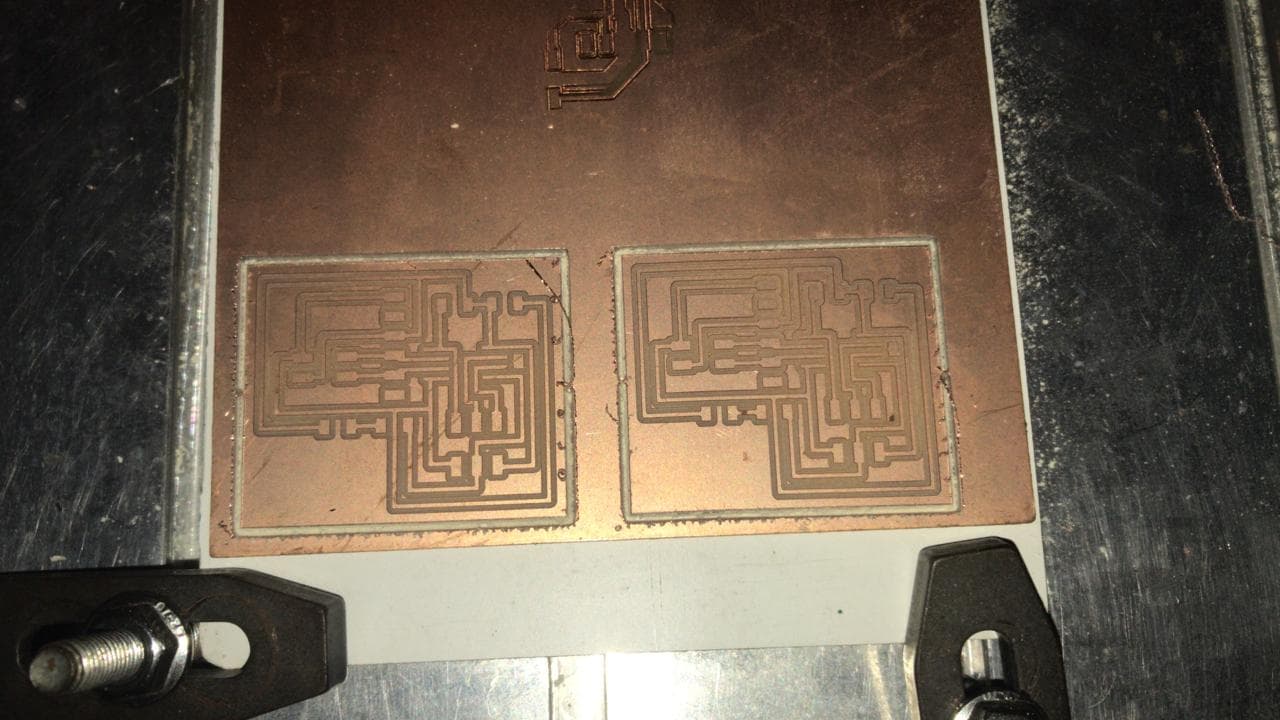
Milling the board
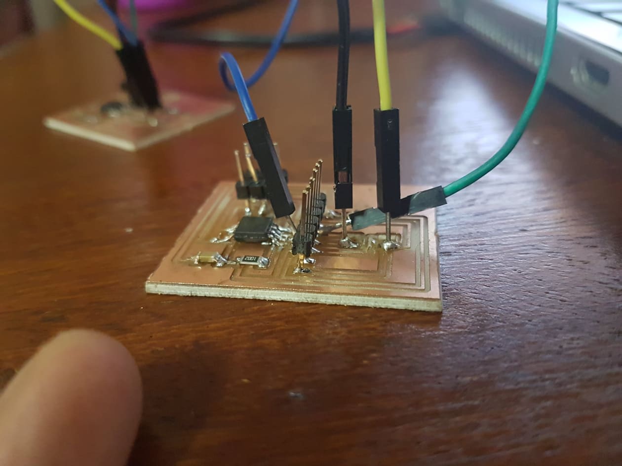
Soldering the components
The components i soldered on the board are :
-FTDI pinheader
-ATtiny 45
-2x2 pinheader
-AVRISP
-10K resistor
-1uF Capacitor
-1K resistor
-LED
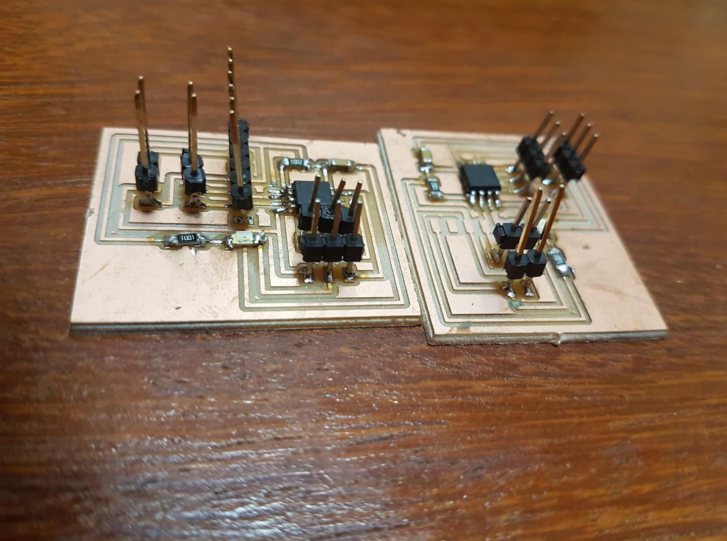
After soldering the components ,the boards should look like this.
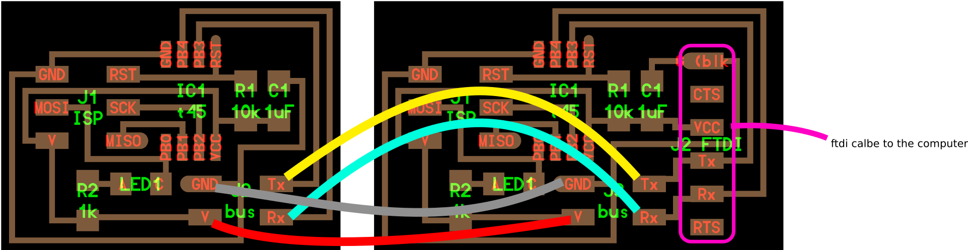
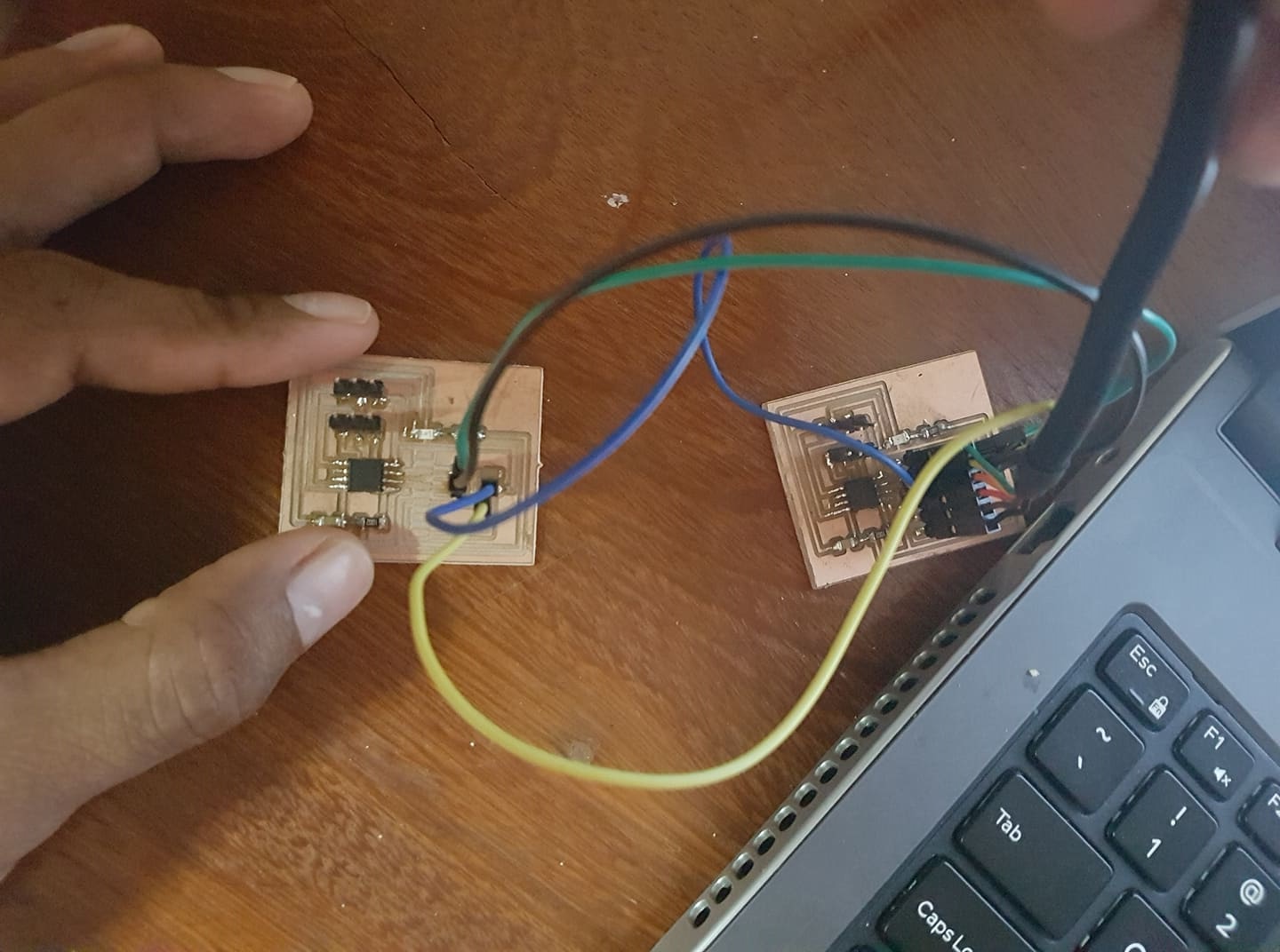
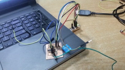
Wiring the boards
For wiring the boards i used female wire jumpers.On both boards there are TX,RX,GND and VCC and you have to connect the TX and RX on both boards voor communication and the VCC and GND for powering the boards.
**I also tried to switch the wires from the TX and the RX by connecting TX from board 1 with RX from board 2 The other way also RX from board 1 and TX from board 2 but it didn't work.Only the LED from the bridge goes on.
Programming the boards(First test)
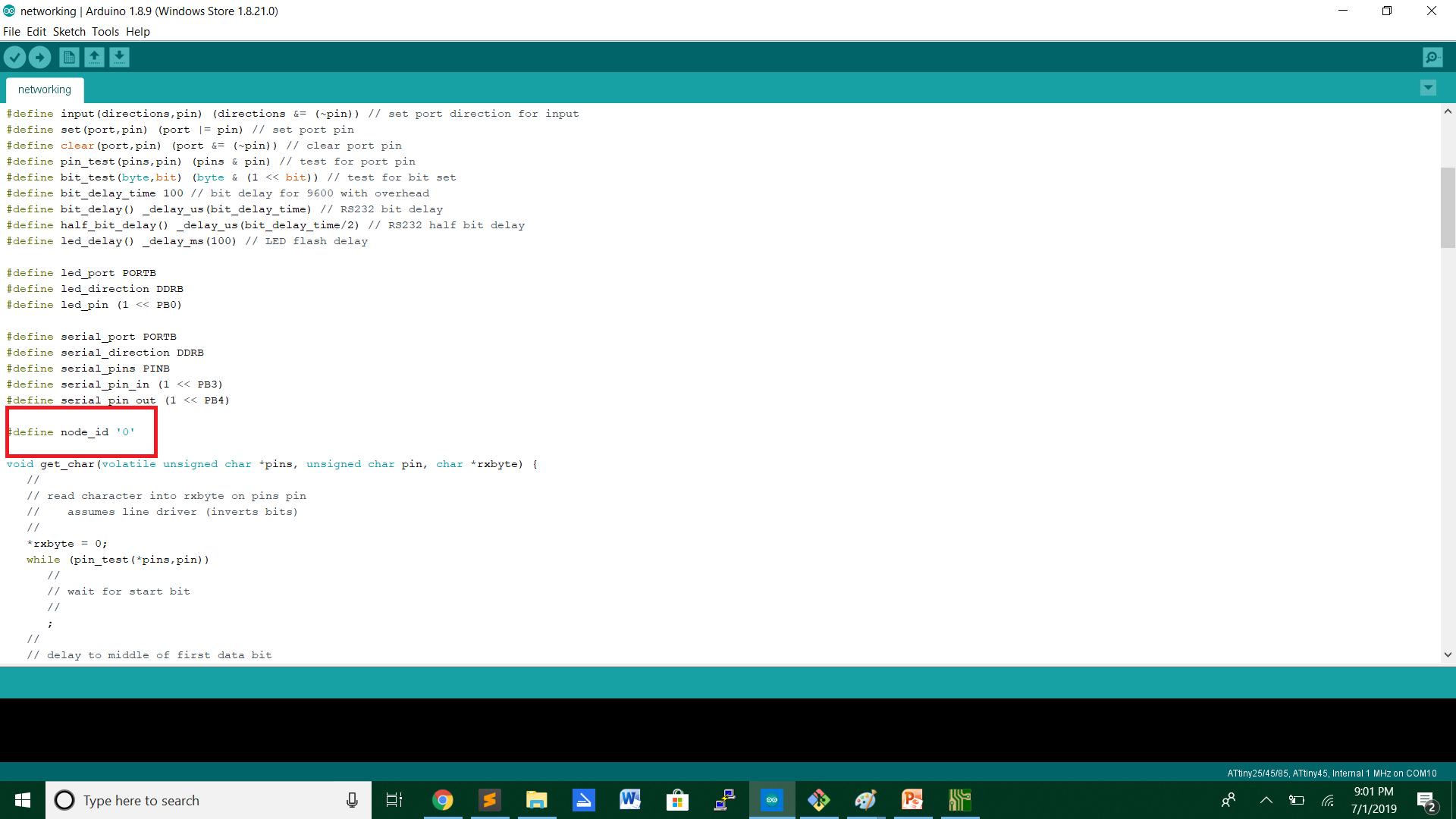
For programming the boards i used the Fab ISP and also Neil's code for the serial communications.By uploading the code for the Bridge i left the #define node_id on '0' and for the Node i changed the #define node_id to '1'.This means that the bridge and the node have there ID.
Programming the Bridge board with the node_id "0"
Programming the Node board with the node_id "1"

Bit Delay time
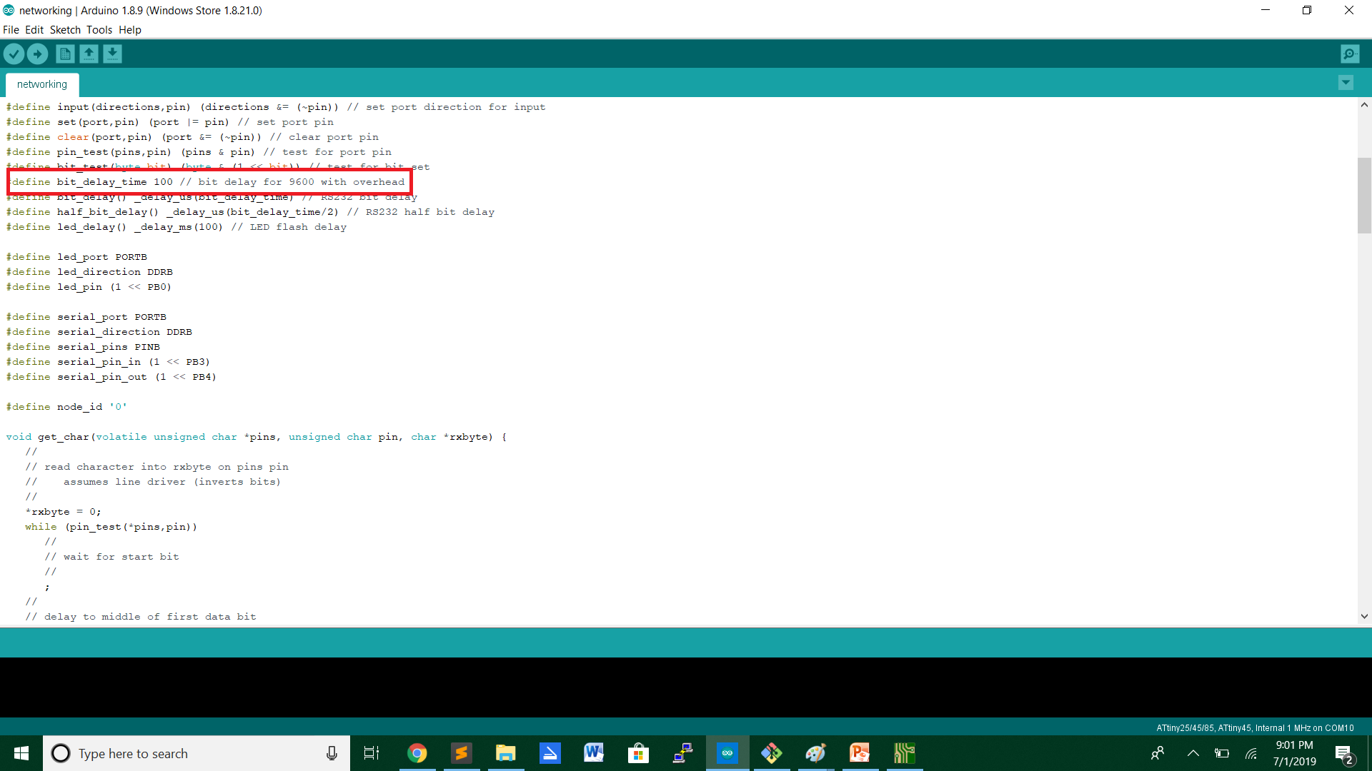
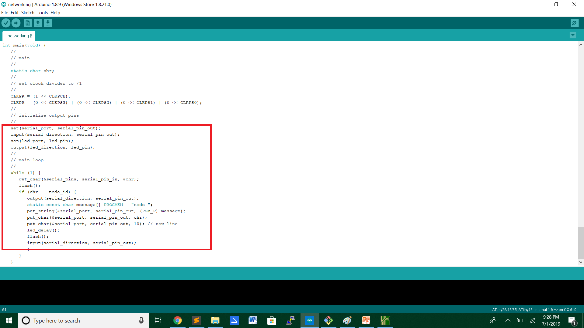
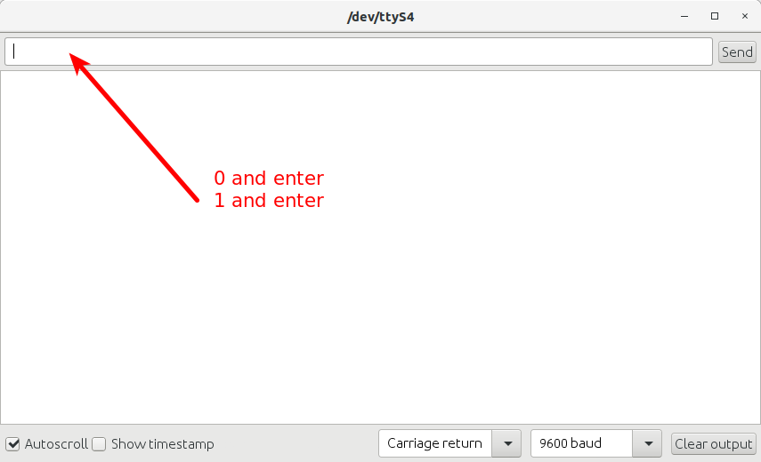
Code for serial output ,when pressing "0" or "1" it will run the code to make the LED flash.It will get data from the output to perform the action.
Problems
Problems i had when wiring the boards is that the traces of the VCC,GND,TX and RX went of the board.So i soldered jumper wires on the end where the traces went of.
So after soldering the jumper wires i tested the boards.
Testing
Programming the boards(Second test)
For the second test i tried to put a external button on the bridge board to work on the LED from board two.In this case the LED wil stay ON on both boards and then when the button is pressed it will perform by blinking the LED rapidly.
First i programmed both boards with the same code.For the serial connection i used pin 3 and 4 as it says in my schematic that is the RX and the TX and for the button i used pin 1.
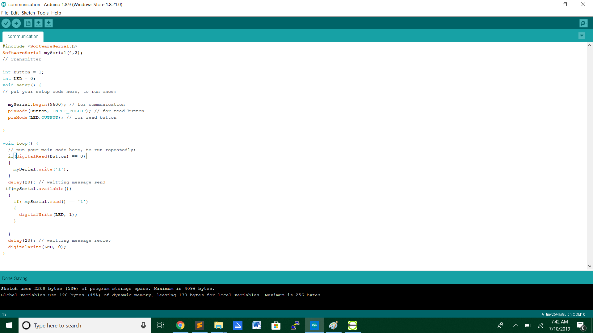
This is the code i programmed on both boards and after programming both boards with the same code i wired both both boards with each other.VCC and GND from both boards and RX from board 1 with TX from board 2 and TX from board 1 with RX from board 2.
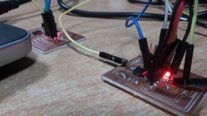
After wiring the boards i connect the FTDI cable on the board and started testing.The outcome is:
Third Test with arduinos
For the third test i used two arduinos that will work in serial.One will run as a Transmitter and the other one as a Reciever.That means one has to send the message to the other arduino and the other must recieve the message.The serial communication will be via the RX and TX ports on both boards and in this case i will use a Arduino Uno and a Arduino Mega.
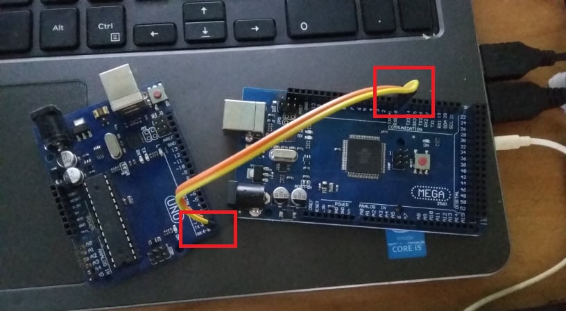
The arduinos have to communicate together to send data.In the picture you see the RX and TX connection on the two boards.RX from the Arduino Mega is connected to the TX of the Arduino Uno and the TX to the RX of the Arduino Uno.The TX and the RX pins means Recieving as stands for RX and Transmitting stands for TX.
Wiring the Arduinos
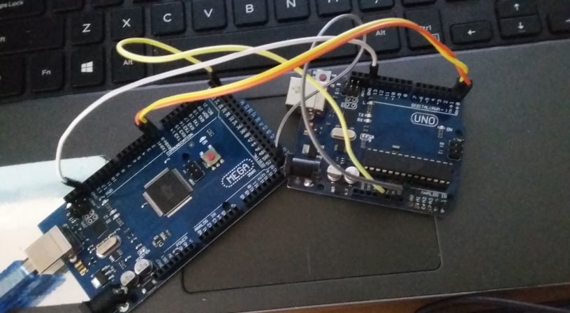
For wiring the arduino i used male to male jumper wires and took power from the mega from thr Mega for the uno.
Programming the Arduinos
The Arduino Mega will be programmed as the Transmitter and the Arduino Uno as the Reciever.For the Arduino Mega i will use this code :
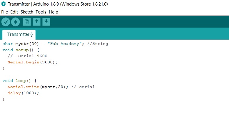
The transmitter will send data to the Reciever from TX from the Mega to RX from the Uno.It will also use baudrate of 9600 and the 20 is the lenght of the data.
For the Arduino Uno i will use this code :
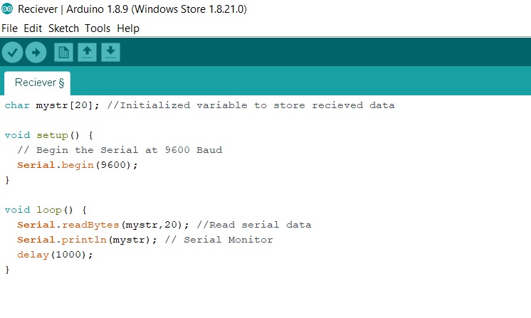
The char mystr[20] is declaring an array of 20 letters.It will initialize it and then restore it.The Serial.readBytes(mystr,20) means that it will read the serial data and then print it out with Serial.println(mystr) with a delay of 1000ms.
Testing the code
First test
Second test
The arduino are communicating by serial but the reciever is getting weird signs.
Third test
Files
Routes NC fileCut NC file
KiCad file
Networking Code
Networking test 2 Code